CLUViz Geometric Algebra Animation Software

CLUViz Explanation
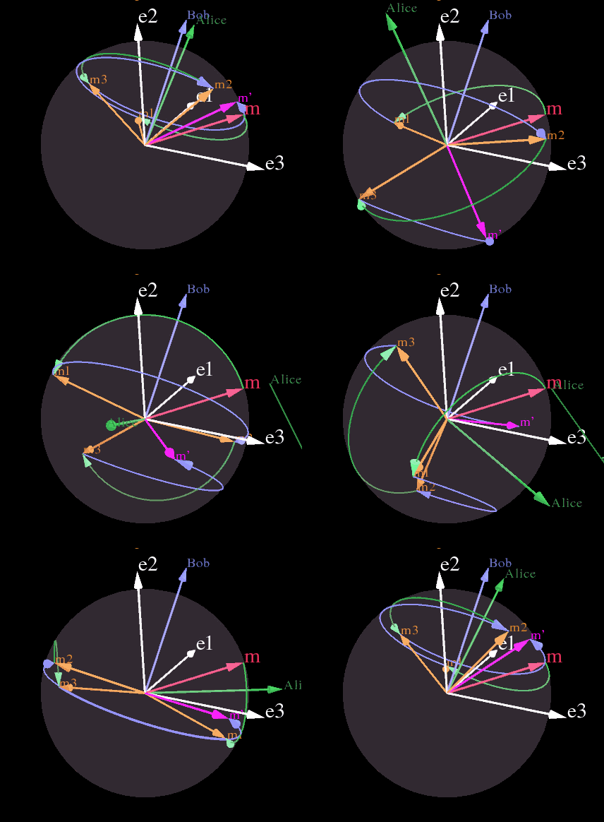
As a part of our project, we've developed a series of images and animations using CLUViz to visually demonstrate how an encryption system based on rotations in 3-dimensions works in accordance with the Double-Padlock Protocol. CLUViz is a freely available software tool for 3D visualizations and scientific calculations that was conceived and written by Dr. Christian Perwass. CLUCalc interprets a script language called ‘CLUScript’, which has been designed to make mathematical calculations and visualisations very intuitive.
Follow the link http://www.clucalc.info/ for more information regarding CLUCalc and http://www.raytrix.de/tl_files/downloads/CLUVizSetup.exe to download the software.
A short YouTube video has been created as a tutorial on how to use the CLUViz software, with an explanation/walkthrough of the CLUViz work done in this project and is supplied on the Final Youtube Videos page of the wiki.
3D CLUViz Work

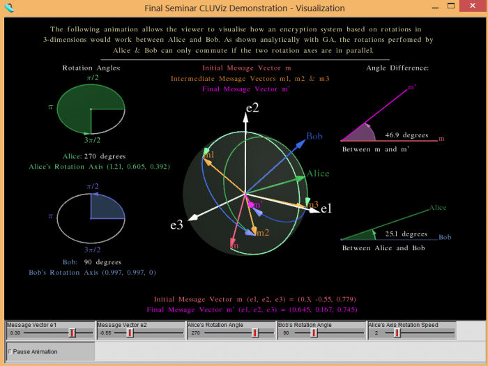
The screenshot to the right shows our 3D-CLUViz animation that was shown in our Final Seminar. It shows a 3-dimensional sphere in 3D Euclidean Space, with the associated based vectors e1, e2 and e3 outlined in white. As demonstrated by the analytical proof of commuting rotations in 3-dimensions above in Analytical Work, the initial and final message vectors m and m' will only be the same if Alice's Rotation Axis and Bob's Rotation Axis are parallel or either of their Rotation Angle's are equal to 0 degrees which is sucessfully demonstrated through this animation, which can be viewed and downloaded on the CLUViz page on the wiki. Through some minor mouse control, the sliders and the support diagrams this program allows viewers to visualise exactly how an encryption scheme implemented with 3D rotations would work and look. It allows the user to change the rotation angles of each rotation axis (green and blue vectors) and the elements e1, e2 of the initial message vector in real time (mid-animation) in order to personalise the experience.
The initial message vector m is shown in red, the final message vector m' is shown in purple and each of the intermediate message vectors m1, m2 and m3 are shown in orange.
Sliders
Sliders at the bottom of the visualisation allow the user to interact with the module and change various elements to gain a better understanding of how it works.
- Two sliders are used to alter the e1 and e2 elements of the initial message vector m, with the e3 element being automatically set to the highest value that ensures that m isn't greater than a unit vector in length.
- Two sliders are used to alter the rotation angle of Alice and Bob between 0 and 360 degrees. Naturally the initial rotation of each is considered to be a clockwise rotation, while the second is counter-clockwise.
- The final slider is used to alter the rotation speed of Alice's Rotation Axis to 1 of 8 different speeds. An option is also provided to halt the animation at any stage, allowing the user to take a closer look.
As mentioned, the animation is conducted through the movement of a single element- that being Alice's Rotation Axis. This movement, allows the user to accurately determine how the difference between the initial and final message vectors alters with the difference between Alice's and Bob's Rotation Axis. As you can see, at the exact point where Alice's Rotation Axis crosses over with Bob's Rotation Axis, the initial message vector crosses over with the final message vector, hence indicating that the four rotations commute. This is further demonstrated via the support diagrams shown to the sides of the main animation.

Support Diagrams
Four support diagrams are used in order to assist those less familiar with the underlying concepts with understanding the process.
- Two support diagrams are used to depict the user chosen rotation angle for both Alice and Bob as a disk.
- Another support diagram is used to display the angle difference between Alice's and Bob's Rotation Axes on the plane in which they both reside.
- Another support diagram is used to display the angle difference between the initial and final message vectors on the plane in which they both reside.
As mentioned previously there are three situations in which the initial message vector will equal the final message vector and each of these are successfully represented by these support diagrams. As such, each of these support diagrams complement each other in providing a clear visual depiction of the commuting rotations. In the case of one of the rotation angles being equal to 0 degrees, you will see the initial message vector m equal the final message vector m'. Also, when Alice's Rotation Axis crosses over with Bob's Rotation Axis and hence the angle between them equals 0 degrees, we will see from the other support diagram that the two message vectors m and m' are also equal.
These second two support diagrams complement each other in providing a clear visual depiction of the commuting rotations.
4D CLUViz Work
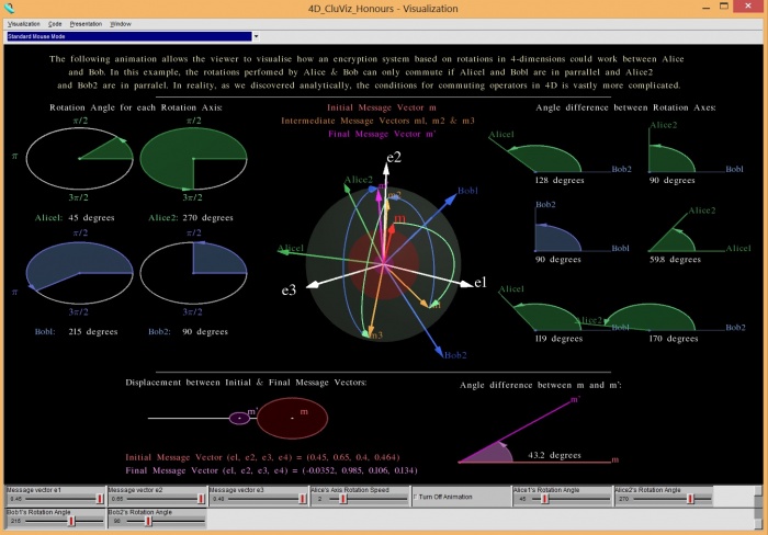
The next step after programming the 3D rotations was to attempt to animate the rotations in 4 dimensions to help give us a better understanding of how they work and hopefully provide us with some conclusive information on whether the rotations could be utilised for secure encryption. In order to represent the 4 dimensional rotations, the previous 3D program was used as the foundation however with several additions.
An additional rotation axis was added for each Alice and Bob bringing the total number of rotation axes to four, as two rotation axes were needed to perform each rotation in 4 dimensions. As a result, two support diagrams were added to allow the user to alter the rotation angles of the new rotation axes. Also, as with the 3 dimensional visualisation, we wished to show the vector displacement between each pair of rotation axes during animation to show how it affects the difference in the initial and final message vectors. As a result, five more support diagrams were added to the right.
In order to depict the 4th dimension for the initial and final message vectors, two spheres were added as shown in red and magenta. The magnitude of each sphere represented the e4 component of each the initial and final message vectors, with the remaining (e1, e2, e3) elements being represented by the 3D vector as in the previous program. Hence, it was programmed that the initial and final message would only equal when the vectors overlapped and the two corresponding spheres were of equal magnitude. However, as known from our other 4D GA work, the conditions for which the two independent 4D rotations can commute are vastly more complicated than we had originally anticipated and as such we ran into difficulty in making these rotations viable, valid and consistent with the theories behind them. We got to the point with our theoretical work that forced us to start looking into higher dimensions and as a result, the 4D visualisation became obsolete.
Difficulties & Possible Extensions
Over the course of the development of both the 3D and 4D CLUViz animations a bunch of possible extensions were identifed. Most of which were features that we attempted to implement and had no luck with as a result of the difficulties faced or the suspected time demands. The main of which, was Mouse Control, where we ideally would've loved to have it so that the user/viewer could interactively control each of the rotation axes and attempt to line them up with one another (more so for 3D) in order to show commuting operators. This was initially suggested by James, as he loved the prospect of the visualisation being like a 'game'.

This became difficult however, as the mouse control was very hard to control and it's implemented in such a way so that by moving the mouse around the length of the vector itself is altered as well as the direction (which caused a unit vector of length 1 to rapidly grow to 100x larger). In an attempt to rectify this problem, instead of displaying the actual rotation axis a unit vector in the direction of each rotation axis was shown, hence giving the impression that you're simply moving the axis around. This was a simple fix, as the length of the rotation axis makes absolutely no difference to it's functionality.
Hypercube
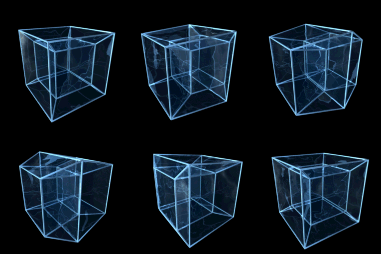
In accordance with the original project description, it was suggested that we attempt to program an animated hypercube (also known as a tesseract). This would have helped viewers fundamentally visualise 4-dimensions rather than rotations in 4-dimensions as shown by the other 4D CLUViz work, however due to the difficulty of programming such a visualisation for what we percieved to be of little value to the project we decided not to program it- however it's noteworthy that efforts were made with CLUViz and with more time it would've been completed. For more on 4D projections, please follow the link - http://eusebeia.dyndns.org/4d/vis/10-rot-1
“In geometry, a hypercube is an n-dimensional analogue of a Square (n = 2) and a cube (n = 3). It is a closed, compact, convex figure whose 1-skeleton consists of groups of opposite parallel line segments aligned in each of the space's dimensions, perpendicular to each other and of the same length.” http://en.wikipedia.org/wiki/Hypercube
Current Code
The final version of the code is included here: 3D Visualisation & 4D Visualisation
After having gotten some background information on 3D & 4D rotations from the reports and/or independent wiki pages, we highly encourage you to follow the link above to download the CLUViz software and our code to have a play around. Naturally, it's recommended that you start with the 3D animation and then move on to the 4D animation if you wish to grasp how 4D rotations could look. All the code if sufficiently commented and it should be relatively easy to navigate throughout the code if you wish to edit elements for whatever reason.
See also
- Timing-based key agreement
- Timing Based Encryption: Test Case 1
- Timing Based Encryption: Test Case 2
- Timing Based Encryption: Test Case 3
- Timing Based Encryption: Test Case 4
- Timing Based Encryption: Test Case 5
- Geometric Algebra
- CLUViz Geometric Algebra Animation Software
- Secure communications without key exchange (main page)
- Secure communications without key exchange? 2013 weekly progress
- Proposal Seminar 2013: Secure communications without key exchange?
- Final Seminar 2013: Secure communications without key exchange?
- Semester A Progress Report 2013 - Secure communications without key exchange?
- Semester B Final Report 2013 - Secure communications without key exchange? 2013
- YouTube Videos