The ball bearing motor mystery 2019
Supervisors
Honours students
Project guidelines
General project description
The ball bearing motor is a mystery because to this day as no engineer knows how it works! No one understands the physical principle at all. Your job is to do some experiments to investigate this motor and why it is that it rotates. Understanding the principle is important. It may not be useful for large motors, but it may be interesting for micromotors and micropumps that have numerous applications.
Abstract
Based on the Huber Effect, the ball bearing motor can be made to continuously rotate in either direction when supplied with either a DC or AC supply. This phenomenon was first observed in 1959 and has since motivated a number of theories to explain the underlying principles behind the motor's operation. This projects aims to test the validity of some of these theories by taking a modular approach to testing the ball bearing motor. An attempt to evaluate the electromagnetic behaviour is made with the use of the a simulation software called ANSYS Maxwell and the relationship between angular velocity and motor torque are also obtained by measuring a physical motor with the use of a load cell and tachometer. The completion of this project hopes to assist future research into the application of the ball bearing motor in micro electrical-mechanical systems whilst leading further research into the Huber Effect in the right direction.
Aim
The main goal is to find out a little more about this motor. Specifically, the aim is to establish the relationship between the angular velocity and the torque because there are actually two theories based on the principles of electromagnetic that are similar but one predicts a linear relationship between speed and torque while the other predicts a squared relationship. By establishing this relationship, the theory that is more likely to be correct can be seen and hopefully future research can be led in the right direction. A secondary goal is to test out a modified version of the ball bearing motor. Instead of applying electricity through the ball bearings, electricity is applied to a solid disc instead. If this works, it will allow for prolonged testing as it will not deteriorate, expand or arc like the ball bearings. This modified motor will then be used to achieve the main goal. The behaviour of the electric and magnetic fields will also be observed by simulating the modified motor using ANSYS Maxwell.
Background
Ever since the Huber effect’s realization, many researchers have made hypothesis’ on how they believe the Huber effect works. Nevertheless, there has been no definite evidence to support any of these theories despite the diverse experiments, consequently the principle of the Huber effect remains unknown. The three main theories hypothesizing this effect are: the electromagnetic force effect, the thermal expansion effect and the electromechanical effect, all of which will be discussed here.
Electromagnetic force effect
The cause for the Huber effect that it uses the electromagnetic force effect, was first proposed in 1977 by Gruenberg - an electrical engineer in Canada. He states that inside each ball bearing there exists an initial current density, J0 with its corresponding magnetic field, B0. When the balls rotate with angular velocity ω, then a new current density, J1 will be generated due to the motion displacement that occurred in the initial magnetic field, B0. A new magnetic field B1 is produced as a byproduct of J1. As the ball continuously rotates then so does the process continuously repeats. The interchanges of between J0 and B1, and J1 and B0 is what causes a torque to occur. One remark is that the initial current density, J0 and the initial magnetic field, B0, is not sufficient to produce a starting torque, meaning that the motor is not capable of self-starting. A torque can only be produced once the motor is manually given a spin [1].
In the ball’s initial state without any external forces, the zero-order fields around the ball: J0 and B0 take shape as shown in part (a) of Figure 1. Once exposed to an external force causing the ball to spin, the fields around the ball in the bearing to take shape as shown in part (b) of Figure 1. Notice how the current density is now shifted to go along the “Y” axis and the magnetic field is shifted to go in the “Z” axis. This orientation of the fields is believed to be the cause of the continuous ball rotation. Through detailed analysis, Gruenberg concluded the relationships between torque, current and angular velocity was a squared one [1].

Thermal expansion effect
Thermal expansion is the increase in volume of a material as temperature is increased, typically expressed as fractional change in volume per unit temperature. Marinov hypothesized that the Ball Bearing Motor is a thermal engine, where it is able to produce motion from electricity without the use of magnetism. He states that the torque (or the main cause of the rotation) is from the thermal expansion of the balls in their bearings. That the contact points between the ball bearing and the races is where it heats up the most, causing the ball bearings to physically expand, yielding a small “bulge” at that point. Noting that not the whole ball becomes heated but only contact points of the ball as shown in Figure 2 with red dots. At these points is where the ohmic (junction between two conductors with linear current) resistance is much greater than the resistance across the entire ball [2].

This is where there ball dilates slightly, and since both the balls and races are made of firm steel; a slight dilation of the ball will create large torque. The motor will then rotate in the direction of provided initial torque. The motor undergoes its rotational movement through the repetitive heating of the ball bearing contacts with its electrical contact with the races. During the rotation, the ball’s “bulge” moves from one position to the next and the radius of the “bulge” becomes equal to the radius of the ball. This radius becomes bigger and bigger with more torque produced, resulting in a mechanical motion. There is not enough evidence to support Marinov’s theory, however the fact that the ball bearings become significantly hot and deteriorate, give reason to not neglect such a theory.
Electromechanical effect
In 1973, the physicist, Polivanov, proposed that Electromechanical was cause of this Huber effect. That the discharge takes place at the contact points between the ball bearings and the races, producing a force sufficient enough to sustain rotation. This force is produced by the applied voltage with an assert being that the current is prone to flow in the opposite direction to the applied voltage. The interactions between the current and the magnetic field causes a disturbance to the symmetry of the current and flux confined by previous contact points. As the points of contact are being continually established through rotation, the force is sustained [3].
In Figure 3, when the ball starts spinning, the old contact point shown in the green circle of part (b) is no longer the contact point. This in turn emerges a new current distribution without neglecting the old distribution, therefore the symmetry is disturbed. Hence the ball will continue to rotate from the momentum of the event of plasma discharge.
_Cross-section_of_current_distribution_in_a_stationary_ball._(b)_Cross-section_of_new_current_distribution_when_the_ball_is_rotated..png)
Specific tasks
- Step 1: Get the workshop to construct a ball bearing motor. It is simply a metal shaft with two ball bearing races either end. If you connect a power supply (eg. a car battery) across the two races it spins at over 1000 rpm and it doesn't matter if it is AC or DC! The objective is to film it working using your smart phone and create an entertaining YouTube video demonstrating it working. This video will be something visual for your presentations and is very important.
- Step 2: Use COMSOL to simulate the motor to see if you can investigate what happens in simulation. The trick here will be to simulate simpler versions of the motor that we will show you. The full ball bearing motor is too complex to simulate first off, so we must simplify.
- Step 3: Characterize the motor. Using an encoding wheel and a photosensor, plot curves of torque versus angular velocity of the motor. For reasons we will go into later, the ball bearing motor itself is not easy to characterize. So the idea is to capture the principle in another way that is simpler. You can get a same effect by getting a metal disc to rotate in liquid metal. We'll show you this idea in detail when you get started. Because mercury is poisonous we will not use that. There are safe non-toxic metals such as gallium and various alloys of gallium with low melting points. Do some research and make a table of these liquid metals, showing their their properties and their cost. We will then select a metal that fits within your project budget. The quantity we can get at reasonable price will also determine the size of your liquid contact motor.
Deliverables
Semester 1
- Start Project Work (Week 1)
- Proposal seminar (Week 6)
- Thesis draft (Week 12) - only one report needed in wiki format
Semester 2
- Ball Bearing Motor Mystery YouTube video (Week 3)
- The reactions of metals with Gallium YouTube video (Week 7)
- Project exhibition 'expo' (Week 12)
- Final thesis (Week 13) - only one report needed in wiki format
- Final seminar (Week 13)
- CD or stick containing your whole project directories (Week 13)
Weekly progress and questions
This is where you record your progress and ask questions. Make sure you update this every week.
Conclusion
In conclusion, the experiments conducted in this project supports Gruenberg's electromagnetic theory as the modified motor did not work and the relationship between torque and angular velocity was found to be a squared one. The result of the simulations and from testing the modified motor have given reasons to not neglect the electromechanical theory suggested by Polivanov instead. However, it is possible that the modified motor did not work due to the size of the motor. Future testing of the modified motor should take this into consideration.
Approach and methodology
Use a dual approach of performing the actual experiment with an encoding wheel and using COMSOL to simulate the effect. You may also consider simulating "Faraday's needle," which is a similar effect. Use COMSOL as a tool to plot fields and find out what it is going on.
Possible extension
You need to figure out how to account for any viscous drag caused by the liquid metal. Perhaps you can perform your experiment with different surface areas of the disc dipping into the liquid metal. You could try just using water instead of metal. The problem with water is the discs will rapidly oxidize. But it should not be expensive to get discs with thin gold plating to prevent this.
Expectations
If you solve the ball bearing motor mystery that is great. However, as it is unsolved for over 50 years we won't mark you down for not solving it. What we expect to see is a structured logical approach to both your lab and COMSOL experiments. If you can definitely eliminate any effects this would be great.
- It is important to regularly see your main supervisors. Don't let more than 2 week go by without them seeing your face briefly.
- You should be making at least one formal progress meeting with supervisors per month. It does not strictly have to be exactly a month, but roughly each month you should be in a position to show some progress and have some problems and difficulties to discuss. On the other hand the meetings can be very frequent in periods when you have a lot of activity and progress to show.
- The onus is on you to drive the meetings, make the appointments, and set them up.
Relationship to possible career path
The project impacts on the areas of micromotors, micropumps, microelectromechanical machines (MEMS), and electromagnetics.
See also
References and useful resources
If you find any useful external links and resources, list them here:
- Method to measure torque
Figures
-
 Figure 1: Gallium experiment setup
 -
 Figure 2: Ball bearing motor experiment setup
 -
 Figure 3: Tachometer's laser lined up with encoder wheel
 -
 Figure 4: Torque arm pressing against load cell
 -
 Figure 5 - Part 1: Arduino torque code
 -
 Figure 5 - Part 2: Arduino torque code
 -
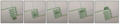 Figure 6: Magnet passsing through coil of wire on Ansys Maxwell
 -
 Figure 7: Simulated current behaviour of Faraday’s Needle
 -
 Figure 8: Physical setup of the Faraday’s Needle experiment
 -
 Figure 9: Magnet being pushed through coil of copper wire
 -
 Figure 10: Graph of the multimeter’s current readings vs. time
 -
 Figure 11: Metals one hour after being submerged in gallium
 -
 Figure 12: Gallium after one hour of being in contact with the corresponding metals
 -
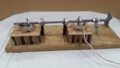 Figure 13: Setup of the Gallium experiment with the ball bearings on the inside
 -
 Figure 14: Torque vs. Time of the ball bearing motor with respect to current
 -
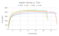 Figure 15: Angular Velocity vs. Time of the ball bearing motor with respect to current
 -
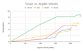 Figure 16: Torque vs. Angular Velocity of the ball bearing motor with respect to current


