The ball bearing motor mystery 2022
Project team
Honours students
- Xinyao Feng
Supervisors
General project description
The ball bearing motor is a mystery because to this day as no engineer knows how it works! No one understands the physical principle at all. Your job is to do some experiments to investigate this motor and why it is that it rotates. Understanding the principle is important. It may not be useful for large motors, but it may be interesting for micromotors and micropumps that have numerous applications.
Abstract
The mystery of the ball-bearing motor is based on the Huber effect, a theory named in memory of J. Huber [1]. There’s been no conclusive experimental evidence to support this effect since then. In 1959, J. Huber found additional rotational force on the conductive wheel pair when the current was supplied and pass through the track [1]. Whether direct current (DC) or alternating current (AC) is used, additional forces that accelerate the wheels can be observed. Milroy first described the ball bearing motor based on the Huber effect [2]. It is composed of a metal shaft with one ball bearing is installed at both ends, as shown in Figure 1.1 [3]. Give an initial beginning torque to the shaft when AC or DC power is applied to the system, and the system will continue to rotate in the starting direction. The motor can rotate in any direction freely.

Aim
According to previous research, many theories have been put forward, but no conclusive experimental evidence exists. Therefore, this project aims to study the physical mechanism behind the ball-bearing motor. This project will build physical models using relatively small size ball bearings. The small sizing can reduce the working current. Then, distilled water will be applied to the system to reduce the overheating and self-destruction effect. In addition, the liquid metal will be used in a modified system to reduce the system friction force. The Arduino board, LCD scream, speed encoder module and load cell will be used to collect data, which will be used to establish the relationship between angular velocity and torque. Meanwhile, simulation experiments using the software COMSOL will be performed in parallel with the physical experiments. It is used to perform the experiment in ideal cases and support the physical experiment results through software calculations.
Background
None of the existing hypotheses about the physical mechanism behind the Huber effect can contradict other hypotheses or summarize conclusions. Three representative assumptions are the electromagnetic effect, thermal expansion, and plasma discharge.
Electromagnetic effect
Grunberg initially hypothesized that the Milroy motor phenomena were caused by an electromagnetic effect. [3]. Each ball in the bearing has the properties of magnetic field B0 and volume current density J0. Because current passes between the contacts on the inner and outer rings, it is assumed that the ball’s angular velocity is ω. The primary magnetic field B0 will be generated, and the secondary volume current density J1 will be generated according to the movement of B0. The process repeats as the ball rotates, which leads to the redistribution of associated magnetic field B1 and electric field E1 and charge. The primary torque source results from the interaction between B1, J0 and B0, J1. Grunberg’s research shows that torque and vector ω. The direction is consistent, so the motor will produce rotating torque only when running, and there is no starting torque. At the same time, he proposed that the speed is directly proportional to the current square based on the analysis of static Maxwell equations.
T = k * ω* I^2 (1)
where I = sqrt (a + b * ω) (2)
However, Weennink proved that these relations are incorrect in algebra [4]. Further on, Moyssides and Hatzikonstantinou demonstrated that there was zero first-order torque [5] [6]. In addition, Weenink found that the calculated value of the ball’s second-order torque is also equal to zero [4]. Hatzikonstantinou and Moyssides put forward that the current of the motor shaft causes the magnetic field B0 and the induced current J0, the ball and its vicinity according to the electromagnetic force generated by the interaction between the induced current, applied current and its magnetic field [4]. The rigorous torque calculation involving Maxwell’s equations discovered that force is the primary contributor Eq.(3). Their conclusions are consistent with the square law equation of the ball bearing motor torque Eq.(1) as well as the nonlinear speed current relationship [4].
F = J × B0 (3)
Thermal Expansion
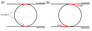
Marinov assumes that the ball-bearing motor is a heat engine rather than an electromagnetic motor [9]. The increase of ohmic resistance leads to the expansion of the ball size, which causes the contact point with inner and outer races to become hot, as shown in Figure 2.1. This leads to the expansion and elongation of the ball bearing at the contact point. When the motor is stationary, the extension of the ball will lead to the seizure of the bearing. Still, during the initial rotation, the elliptical point will generate torque in the rotation direction to maintain the movement. All the balls in electrical contact with the bearing housing are involved in the cyclic process, so the balls rotate continuously. Marinov also proposed that the engine cannot realize self-starting under the condition of perfect smoothness and geometrical perfection according to the thermal expansion theory [9]. The ball surface deviation causes the occasional spontaneous start. This theory has an obvious defect which is that the thermal effect usually has a long time constant, which means that it seems impossible for the ball to extend and contract at a medium speed. Although the theory of thermal expansion has been questioned, it cannot be ignored because there is no experimental evidence.
Plasma Discharge
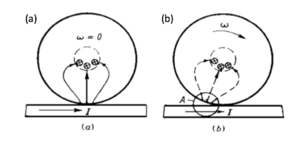
In 1973, Polivanov, Netushil and Tatarinova proposed that the Huber effect should be attributed to plasma discharge [10], a phenomenon of spark discharge on the surface of the ball and racetrack, resulting in a force sufficient to maintain rotation. According to Lenz's law, the induced current tends to flow in the opposite direction to the induced current [11]. In a magnetic field, the induced current interaction produces force, which interferes with the current symmetry and magnetic flux distribution created by point contact [11]. Figure 2.2 schematically depicts the continuous process of wheels and axles on the guide conductor track. Netushil proposed an expression of the repulsion force between the inner ring and the ball in his research [12].
F = k * I^2 (4)
Simulation
Design
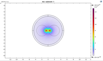
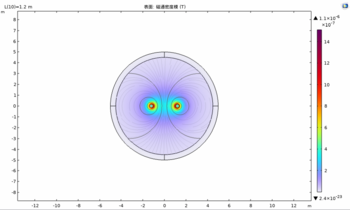
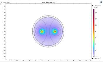
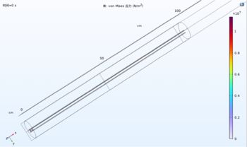
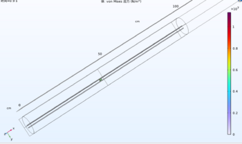
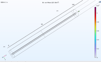
Build three related software simulations through COMSOL about electrical simulations with moving parts, including two parallel wires, a railgun, and the simplified ball-bearing motor. Then collect data from these simulations and compare it with the calculated data sample to support the physical experiment results.
Result
- Two parallel wires moving apart
- Railgun Projection Motion
- Railgun Projectile Detail
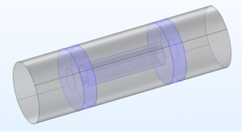
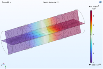
- Simplified Ball Bearing Motor
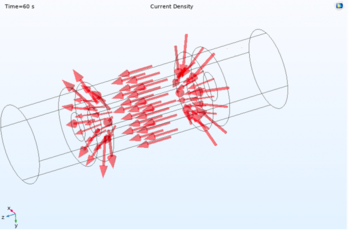
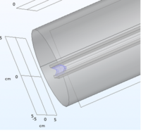
The simplified ball-bearing motor simulation aims to investigate the system’s angular velocity and torque value under different input currents and the relationship between these two parameters. In addition, it presents all the relevant figures for the magnetic field, electric field, current and characteristic curves. Then, evaluate the result to determine which theory fits the result most.
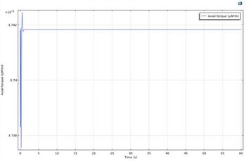
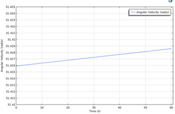
- Torque (Nm) & Angular Velocity (rad/s) versus time (s)
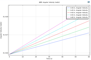
As can be seen from the graph, the torque tends to be a stable linear straight line with time, while the angular velocity also tends to be an increasing linear straight line. However, the torque is actually increasing but with a very small scale that cannot be seen from the figure. The angular velocity from the actual physical experiment tends to increase slowly with time because of the overheating and self-distortion issue. However, the simulation generated an ideally case with no friction force and prevented those issues and provided a smooth, increasing linear line shape.
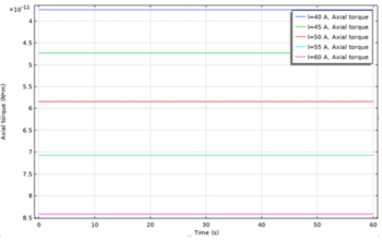
- Torque and Angular velocity in different current situations
Both torque and angular velocity increase with the current. The relationship of each parameter with time is also the same as the previous results. However, the angular velocity in different currents has different curve slopes. The figure shows that the lower current input cases tend to have a smaller slope.
- Torque (Nm) versus angular velocity
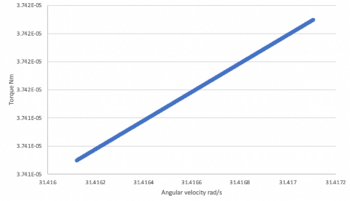
The relationship between the torque and angular velocity is an increasing linear line, which supports the linear relationship theory proposed by Watson et al.
Design
Experiment
Experiment 1 is to construct a physical model of small-size ball bearings. It has a solid metal rod attached to the ball bearing race's inner side. Then, collect the current and voltage values pass through the system.

Experiment 2's system is built based on the first model, which is submerged in deionized water. This experiment will record the angular velocity of the ball-bearing motor inside and outside the deionized water, as well as the current and voltage during the initial state and uniform motion state. The multimeter, current clamp and tachometer will be used to achieve this process. Then compare the results with the first model.
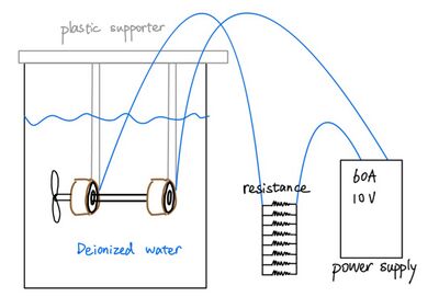
Experiment 3 is to build another ball-bearing system based on the first model to optimize the defects further.The objective plan is to lower the system friction force to improve the self-distortion issue and obtain a more precise result of the relationship between angular velocity and torque.The liquid metal gallium-indium is selected for this model as a relatively low viscosity and can reduce the friction force of the system.

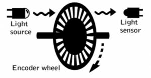
Measurement of angular velocity and torque
The Arduino board, speed encoder module and load cell can be used to collect real-time data sets. The speed encoder module includes a speed measuring sensor, encoder counter and infrared optical detection module. The light source passes through the rotating encoder wheel and is collected by the light sensor. The slots in the encoder disc enable the receiver to turn on and off when it is rotated. The load cell weight sensor can convert the pressure force into an electrical signal. A load cell amplifier is needed to handle the relatively small electrical signal that the load cell produces. In this case, an HX711 load cell amplifier is used. Both systems can generate the real-time data series using the Arduino software after wire connections and the coding process.

Result
Objective 1 of the first ball bearing motor aims to measure the starting current and voltage as well as the current and voltage during the operation. The ball bearings achieved the highest temperature of around 80 degrees during the experiment. The high temperatures might be the result of the friction force. There was also a spark that occurred around the connecting area between the copper stabiliser and wire.

Conclusion and discussion
The angular velocity and torque relationship are linear based on the simulation experiment. This supports the theory proposed by Watson et al. However, there’s still no conclusive experimental evidence provided with this project. Although the software simulation result supports the linear relationship theory, the conclusion cannot be made based on one simulation. Further physical studies should be performed to understand the physical mechanism behind the ball-bearing motor and hopefully bring great potential applications in microelectromechanical systems (MEMS).
The project has achieved all software simulations and one physical experiment. The two parallel wires simulation shows the magnetic attraction force and repulse magnetic force acting on the wires and proved to have similar results with calculated magnetic force. The rail gun simulation shows the projectile acceleration motion based on the attraction magnetic force. In addition, the simulation by current input in parallel with the same directions proves that the magnetic repulse force can also perform the railgun projection just with an extra initial force. These simulations set the foundation of the final simplified ball-bearing motor model. The simulation result of the final model shows the linear relationship between angular velocity and torque. The first physical experiment proved the overheating and self-destruction phenomenon of the ball-bearing motors. However, the modified models were not successfully performed due to the large current input demand for these systems. The ball bearings purchased online have a limited size range and friction efficiency. The poor performance of the ball bearings leads to the large current input demand, which is unsafety to operate. The improvement plan of this project is replacing the ball bearings, allowing the miniaturization of physical models and safe experimentation.
Future work
The main problem encountered in completing the project was that the size of the purchased ball bearing was limited, and the ball bearings this project obtained were not small enough. Therefore, the current required for the experiment is still relatively high, which means that the improvement of self-destruction caused by overheating is limited. The self-destruction effect also limits the number and reproducibility of continuous experiments and tests. In the future, various sizes of ball bearings and shafts should be used to optimize and understand the impact of size on motor performance. In addition, not only the size of the ball bearings is limited, but there is also a variety of fiction differences between the ball bearings. Based on the literature review, the friction force within the ball bearings also significantly affects the self-destruction issue. Therefore, ball bearings with lower friction force should be selected in future experiments.
Moreover, this project only considered one effective heat sink liquid of deionized water and one liquid metal to lower the friction force. The experimental result is limited. In the future, multiple effective heat sink liquid and liquid metal should be considered in the experiment. This can bring about the diversity of experimental results and prove the theory with more reliable experimental data. Using kerosene, silicone oil, and mercury will be a great start to enhancing the reliability experiment.
In addition, this project can demonstrate Milroy's thermal expansion theory in future experiments by using ball bearings of conductive metals with different thermal expansion coefficients and controlling other variables in the experiments. Linear temperature expansion coefficients are different for different materials. For example, silver's linear temperature expansion coefficients are 19.8E-6 m/(m°C) while the linear temperature expansion coefficients of copper are usually around 16E-6 m/(m°C) [22]. Still, the conductivity coefficients of these two metals are very close. According to the description of thermal expansion theory, the ball-bearing race generates ohmic heat in the energized state. The contact point between the small ball, the outer ring and the inner ring of the ball bearing race will produce a bulge, and the radius of the bulge is approximately equal to the radius of the small ball [7]. After an initial force is given to the bearing, a driving torque with changing direction appears inside the bearing to drive the bearing to rotate. Therefore, we can assume that the driving torque of the bearing is different for different materials with the same conductive properties with the same size and construction, and the degree of concavity is also different. When we use the method of controlling variables and change only the material of the ball bearing race, if the measured speed of different models is the same, then the theory can be effectively denied. If the rotation speed of different models is not the same, this also illustrates the feasibility of the Milroy thermal expansion theory to a certain extent.
Another area that can be improved in the future is the research on motor simulation. The operation of COMSOL requires rich experience. At the beginning of the experiment, our team spent a lot of time understanding and practising with the software. This delayed the overall progress of the project. The improvement can be made in the final model of the simplified ball-bearing motor. The result will be more precise and reliable if the full ball-bearing model can be built inside the software.
References
[1] J. Huber, "Electrodynamische Kraftwirkungen au Einem auf Eisinbahschienen Beweglichen Radsatz," Elektrotechnik und Maschinebau, vol. 76, pp. 169-74, 1959.
[2] R. A. Milroy, "Hydrodynamic gyroscope," Journal of Applied Mechanics, vol. 34, pp. 525, 1967.
[3] H. Gruenberg, "The ball bearing as a motor," American Journal of Physics, vol. 46, pp. 1213-9, 1978.
[4] A.P. Lauterbach, W. L. Soong and D. Abbott, "Investigation of small motors operating under the Huber effect," Proceedings of SPIE, vol. 4236, pp. 306-18, 2001.
[5] Moyssides, F.G. and Hatzikonstantinou, P., “Study of electrical characteristics of the ball bearing motor.” IEEE Trans. Magn., Vol. 26, No. 4, pp.1274-1281, 1990.
[6] Moyssides, F.G. and Hatzikonstantinou, P., “Ball bearing motors,” IEEE Trans. Magn., Vol. 33, No. 6, pp.4566-4569, 1997.
[7] Watson, D.B., Williams, M.R. and Crimp, C.S., “Ball-bearing motors,” IEE Proc.-A, Vol. 140, No. 4, pp.281-286, 1993.
[8] Joo L. Choo, W. L. Soong, and D. Abbott, " Toward Characterization of Huber’s Ball-Bearing Motor," Proceedings of SPIE, vol. 5649, pp. 719, 2012.
[9] Marinov, S., “The intriguing ball bearing motor,” Electronics and Wireless World, pp. 356-357, April 1989.
[10] Walker, M.B., Chambers Science and Technology Dictionary, 1994 reprint, (Chamber Cambridge 1988), p515.
[11] NETUSHIL, A.V.: "The electromechanical effect of Huber and its development". Elec. Tech., No. 3, pp.57-64, 1992.
[12] Shen, Y., Tay B.K., Thompson B., Soong W.L., B.R. Davis and D. Abbott, “Investigation of the Huber effect and its application to micromotors,” Proc. SPIE Electronics and Structures for MEMS, Vol. 3891, pp.178-183, Oct. 1999.
